D 2 5t r see below the height can be less but it required secondary operations and is far more costly.
Sheet metal bend relief formula.
For bends between 0 and 90 degrees the formula is as follows.
Use the minimum bend dimension values in the charts below for your minimum closeness of cutout to a bend.
ß bending angle for bends between 90 and 165 degrees the formula is.
Form height to thickness ratio to determine the minimum form height for sheet metal use the following formula.
Consider a sheet with a 20 mm thickness and a length of 300 mm as shown in figure 1.
Most sheet metal materials will conform to the calculations.
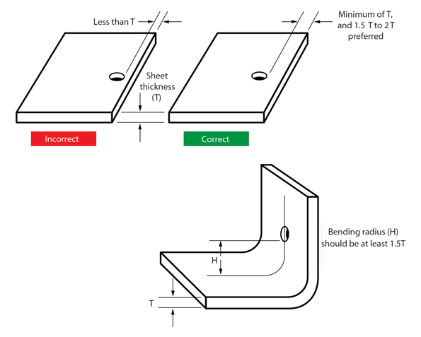
When sheet metal makes a transition from a bend to a flat surface or to another bend it tends to rip and tear.
Refer to the chart for values for folder as well as various press brake tooling combinations.
The diagram shows one such mechanism.
The material thickness will be measured in decimal form not by the gauge number.
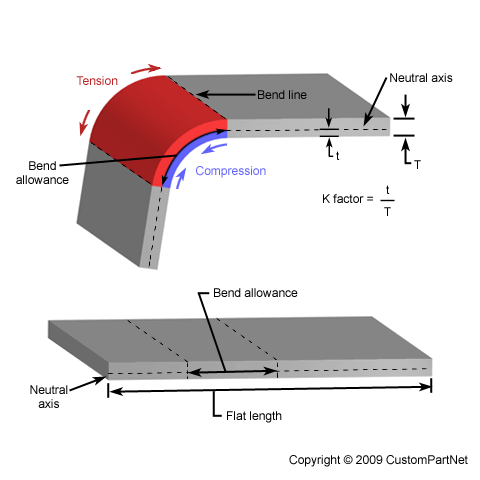
Sheet metal calculator bend allowance equations and calculator.
To eliminate this a bend relief is added so the edge of the sheet metal is perpendicular to the bend.
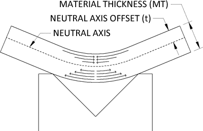
The bend allowance formula takes into account the geometries of bending and the properties of your metal to determine the bend allowance.
The following illustration shows the equation calculation for determining the bend allowance when forming sheet metal.
60 90 and 120 and we will calculate k factor bend allowance and bend deduction for them.
We are going to review three bending scenarios with three different bending angles.
The bend allowance describes the length of the neutral axis between the bend lines or in other words the arc length of the bend.
In general a minimum bend relief is equal to the material thickness plus the inside bend radius.
Geometry of tooling imposes a minimum bend dimension.
This page also includes a link to a on line sheet metal bend allowance calculator.
Therefore the bend allowance added to the flange lengths is equal to the total flat length.
5 edge distortion an exaggerated example of edge deformation is pictured in figure a below.